- I won't stop bugging you until I get the address of your home.
- You fascinate me more than the Fundamental Theorem of Calculus.
- Since distance equals velocity times time, let's let velocity and time approach infinity, because I want to go all the way with you.
- My love for you is like a concave up function because it is always increasing.
Thursday, 31 July 2014
Engineer Charming A Girl
Series DC Motor Calculation
The Example Shows the Calculations done for Series DC Machines:


The Solution:
Wednesday, 30 July 2014
Funny Maths Solution
This is what a student wrote when he was clueless about how to go about the question.

Separately Excited DC Machine Calculations
The Long example captures most of the required calculations on a separately excited DC Machine


Tuesday, 29 July 2014
Short Engineering Joke
Chief engineer: You told me that you would finish the layout in three days.
Engineer: Sure, but not three consecutive days!
The engineer then comes in to talk to his chief engineer.
Engineer: "I'm having trouble with that power supply circuit you put me to work on."
Chief engineer:"OK, let's talk about it, Is it oscillating?
Engineer: "No,it is stable."
Chief engineer:"How is the efficiency?"
Engineer: "About 87%"
Chief engineer:"Is there ringing on the gate?"
Engineer: "Nothing above normal."
Chief engineer:"What about noise and ripple?"
Engineer: "They are well within spec."
Chief engineer:"Then what's the problem?"
Engineer: "The darn thing's on fire!"
© Copyright Mark W. Lund 2008 combined with © Copyright 2013 Mark W. Lund
Joke- Electrical Engineering Interview
INTERVIEW
Subject: Electrical Engineering
Interviewer: Why is a thicker conductor necessary to carry a current in A.C. as compared to D.C. ?
Candidate: An AC current goes up and down (drawing a sinusoid) and requires more space inside the wire, so the wire has to be thicker.
Interviewer: How will you tell if that wall outlet carries AC or DC ?
Candidate: I will put my finger in. If it is pushed away, it is DC. If it gets stuck, it was AC.
Interviewer: How will you reverse direction of an induction motor?
Candidate: I will remove the four bolts at the base, turn the motor around, and put back the bolts.
Interviewer: How do you start a synchronous motor?
Candidate: Vrrrrrrrmmmmmmmmmmmmmmmmmmm (in rising pitch)
Interviewer: Stop! Stop!
Candidate: rrrrrrrmmmmmmmmmmmmmmmmmmmm (in falling pitch)
Interviewer: How do you limit surge current within an integrated circuit?
Candidate: By using a miniature circuit breaker.
INDUCTION MOTOR SPEED CALCULATIONS
The example shows how to calculate motor speed given slip and other parameters:


Monday, 28 July 2014


Magnetic Field Strength- A Level Physics
Example:
In the figure below, determine the point (other than at infinity) at which the total electric field strength is zero.

From the diagram, it can be observed that the point where E is zero lies on a straight line where the charges lie, to the left of the -2.5 μC charge.
Let this point be a distance r from the left charge.
Since the total electric field strength is zero,
E6μ = E-2μ
[6μ / (1 + r)2] / 4πεor2 = [2.5μ / r2] / 4πεor2 (Note: negative sign for -2.5 μC has been ignored here)
6 / (1 + r)2 = 2.5 / r2
√(6r) = 2.5 (1 + r)
r = 1.82 m
The point lies on a straight line where the charges lie, 1.82 m to the left of the -2.5 μC charge.
Wednesday, 23 July 2014
Faraday's Law
Faraday's law
Question: A plane circular loop of conducting wire of radiusAnswer: The area of the loop is
The component of the magnetic field perpendicular to the loop is
where
Likewise, the final flux linking the loop is
The time rate of change of the flux is
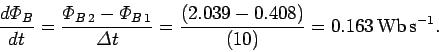
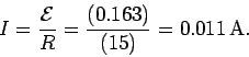
Thus, the emf generated around the loop is
Note, incidentally, that one weber per second is equivalent to one volt.
According to Ohm's law, the current which flows around the loop in response to the emf is
Fleming's Left hand rule - Motor Effect
A current carrying conductor experiences a force if it is placed in a magnetic field.  The direction of the force is found using Fleming's left hand rule.  The force is proportional to:
The formula relating the three quantities is: F = BIl [B – magnetic field strength; I – current in A; l – length in m] The term B is called the magnetic field strength, or the flux density, and is measured in Tesla, T. The magnetic flux density can be thought of as the concentration of field lines. Example: A current of 8.5 A flowing through a magnetic field is found to exert a force of 0.275 N. The length of wire in the magnetic field is 5 cm. What is the value of the magnetic field? |
| Formula first: F = BIl. |
Þ B = F = ___0.275 N ___ = 0.647 T Il 8.5 A ´ 0.05 m |
Tuesday, 22 July 2014
Maxwell's right handed screw/ Cork Screw rule
The figure shows the screw rule used to determine the direction of the magnetic field in a current carrying conductor. It states that if a right hand screw is screwed into or out of a board, the direction in which it rotates is the direction of the magnetic field around the current carrying conductor if the direction of motion of the screw is the direction of current in the conductor.
This can be used to verify the right hand grip rule.

This can be used to verify the right hand grip rule.
Monday, 21 July 2014
The right hand grip rule for magnetic field around current carrying conductor.
The diagram clearly explains the use of the right hand grip rule.

Electromagnetics Constants

Thursday, 17 July 2014
Ten 'Fun and Exciting' Facts About Engineering
From space exploration to the water slide, engineering makes our lives more 'fun and exciting.'
DID YOU KNOW THAT...
- The snowboard was invented by an engineer?
With some engineering twists and turns along the way, the snowboard has become a marvel of geometry, chemistry, and biomechanics. Since the snowboard allows deft turns, ski manufacturers have quickly adopted some of the snowboard innovations, enabling skiers to turn with less effort. - Engineers design running shoes for protection, performance, and comfort?
Engineers understand how much force travels from the ground through the shoe to the foot. Through the work of engineering, weight is distributed throughout the whole foot -- heel to toe. - A civil engineer created the slippery part of the water slide?
A civil engineer designed a pumping system to circulate just the right amount of water to the flume. Without the right flow of water, there is no ride. Additionally, civil engineers have designed the slide to withstand the weight of people, the water, and even the force of the wind blowing on it. - The launch and return of spacecraft, from the Apollo to the Shuttle, is a monumental engineering triumph?
The space program has greatly expanded the world's knowledge base. The technological advancement by engineers in energy, communications, materials, structures, and computers, have made space travel possible. - The Ferris Wheel is considered one of the greatest engineering wonders in the world?
The first Ferris Wheel was created by Pittsburgh, Pennsylvania engineer, George W. Ferris, in 1893. The wheel is supported by two 140-foot steel towers and connected by a 45-foot axle -- the largest single piece of forged steel ever made at that time. - Engineers make interactive television possible?
Engineers are involved in all aspects of interactive TV technology, from designing new cables, to creating new film emulsions, to engineering better sound quality. This technology allows viewers to select any program, film, or game from more than 500 channels. - Engineers play an instrumental role in the theme park industry? Theme park engineers are involved in designing, building, lighting, and even controlling the crowd flow in theme parks around the world.
- Companies and universities are using engineers to form the Virtual Reality and Simulation Initiative? This technology applies computer simulation and visualization to 3-D modeling projects, such as virtual offices.
- Bioengineers are creating a new and exciting medical technology? This technology will utilize virtual reality to help surgeons reconstruct facial birth defects.
- Computer engineers, in conjunction with animators, have created special effects in movies such as "Jurassic Park," "Forrest Gump," and "Interview with the Vampire"? Through "morphing" technology, images are digitally mastered to appear realistic.
Sources:
Baine, Celeste. The Fantastical Engineer. Farmerville, LA: Bonamy Publishing, 2000.
http://www.apegga.com/ (Nike(r) Neers)
http://www.discoverengineering.org/
http://www.greatachievements.org/
http://www.inventors.about.com/
Baine, Celeste. The Fantastical Engineer. Farmerville, LA: Bonamy Publishing, 2000.
http://www.apegga.com/ (Nike(r) Neers)
http://www.discoverengineering.org/
http://www.greatachievements.org/
http://www.inventors.about.com/
Wednesday, 9 July 2014
Circuit analysis using Nodal Analysis Method
The aim of nodal analysis is to determine the voltage at each node relative to the reference node (or ground). Once the voltages are known, currents can be easily calculated.
The analysis follows the following steps:
(1) Pick any node as the voltage reference. Label its voltage as 0 V or the ground. Any value calculated is with respect to this ground or 0 V level.
(2) If any fixed voltage sources are connected to a labelled end, label their other ends by adding the value of the source onto the voltage of the labelled end.
(3) Pick an unlabelled node and label it with X, Y, . . . or any other convention like V1, V2,..., then go back to step (2) until all nodes are labelled.
4) Use KCL to label determine the currents
5) Use the currents and the resistances in KVL to determine the nodal voltages.
The Following example show how to use the analysis method.
Monday, 7 July 2014
Electrical Circuit Analysis using Mesh Analysis
The node method or the node voltage method, is a very powerful approach for circuit analysis and it is based on the application of KCL, KVL and Ohm’s law. The procedure for analyzing a circuit with the node method is based on the following steps.
1. Clearly label all circuit parameters and distinguish the unknown parameters from the known.
2. Identify all nodes of the circuit.
3. Select a node as the reference node also called the ground and assign to it a potential of 0 Volts. All other voltages in the circuit are measured with respect to the reference node.
4. Label the voltages at all other nodes.
5. Assign and label polarities.
6. Apply KCL at each node and express the branch currents in terms of the node voltages.
7. Solve the resulting simultaneous equations for the node voltages
The following example illustrates the method.
A day in the life of an Engineering Student
That is how your life runs as an Engineer. Back to business after this.
 Have a great Week.
Person or Human
I wonder what is the difference between being a person and being human.
 This leaves us wondering. Check the next post to see what your life is all about if you are an Engineer.
No Rest for Engineers
Just to start the week on a light note, check these pictures.
We are continuing with our lessons after this.

When an Engineer thinks he is relaxing, he realizes that in fact he is still working. Check the next post.
We are continuing with our lessons after this.
When an Engineer thinks he is relaxing, he realizes that in fact he is still working. Check the next post.
Friday, 4 July 2014


Series-Parallel Magnetic circuit
Below is an example which shows that you can treat magnetic circuits in exactly the same way that you treat electric circuits. The components that are related are shown below:
Magnetomotive force is the driving force in a magnetic circuit. It is analogous to the electromotive force in the electric circuit.
The reluctance in the magnetic circuit is the opposition to the establishment of flux hence is analogous to resistance in the electric circuit.
The flux in the magnetic circuit is the effect of the mmf and hence is analogous to the current.
Wednesday, 2 July 2014
Basic Formulae used in Electrical Circuits
Below are the basic formulae which an Electrical or Electronic Engineer should know in order to be able to deal with electrical circuits. Some may use them just to pass tests, some to analyse circuits and at a higher level you need them to design circuits.
They should be know and not memorized to avoid confusion.

They should be know and not memorized to avoid confusion.
Tuesday, 1 July 2014
THEVENIN'S THEOREM EXPLAINED BY EXAMPLE
Thevenin’s theorem states that a linear two-terminal circuit can be replaced by an equivalent circuit consisting of a voltage source VTh in series with a resistor RTh , where VTh is the open-circuit voltage at the terminals and RThis the input or equivalent resistance at the terminals when the independent sources are removed.
The method of removing sources has been described in Norton's Theorem. The steps for getting the Thevenin equivalent resistant is again the same as the process for getting Norton's equivalent resistance. The method for getting the Thevenin's equivalent voltage will be described in the example below..
NB: This Example has been taken from www.electricaltechnology.org
Qn. Find the Thevenin Equivalent Circuit across A-B and determine the load current.


Subscribe to:
Comments (Atom)